
OpenFlow is one of the most popular SDN (Software-Defined Networking) protocols. It enables remote control of the OpenFlow switch data layer and managing QoS mechanisms. The first section of the article briefly introduces the layered network model and a reference SDN network model. Next, I will present the OpenFlow protocol used for SDN-OF (OpenFlow) switch communication. Finally, I will discuss the OpenFlow switch logical structure.
Layered network model
A layered network model diagram is shown in Figure 1. It consists of 3 layers:
- control layer,
- management layer,
- data layer.

The data layer implements packet processing and forwards them between network devices. The control layer is responsible for determining traffic flow rules applied within the data layer. The management layer implements configuration functionalities, failure detection and repair, status and resource load monitoring, as well as control access to network elements. It should be noted that all components executing the functionalities of both the data and control layers are subject to management.
SDN network reference model
An SDN network reference model was shown in the ITU Y.3300 presentation and distinguishes between three SDN network layers:
- SDN Application layer,
- SDN Controller layer,
- Network Resource layer.
The aforementioned layers are managed by a multi-tier management function. Figure 2 shows the above layers and their primary functions.
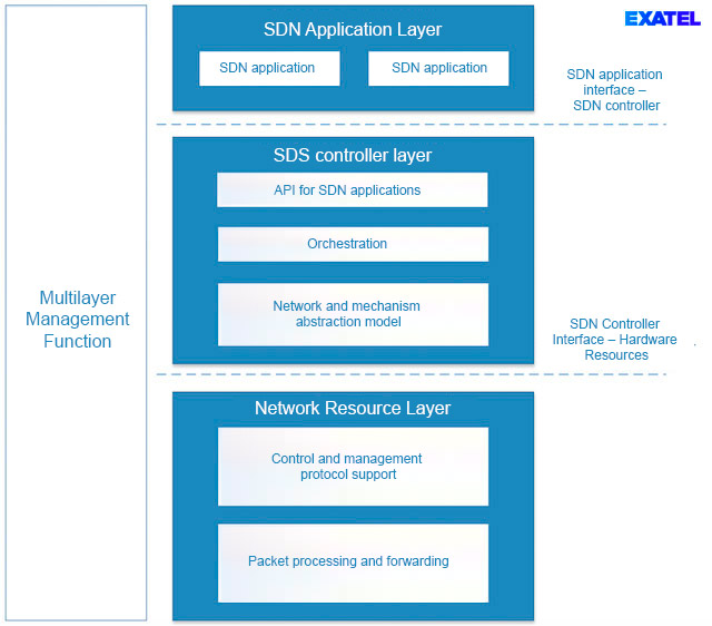
The SDN Application layer is responsible for executing business functionalities (e.g., network services such as L2VPN or L3VPN). It utilizes the programming interface made available by the SDN controller through which SDN apps can control network traffic and manage device resources. This interface is based on an abstract network model. The SDN controller layer enables SDN network orchestration functions. It is responsible for managing device resources and setting up transport connections at the request of an SDN application. It ensures SDN application and SDN control logics independence through introducing an abstract network model and network mechanisms. This model is converted into messages compatible with a given equipment type, upon establishing communication with a given device. The controller and device communicate via the SDN controller – hardware resources interface. This interface controls and manages a network device and can be executed by any number of communication protocols. The main functionality implemented within the network resources layer is processing and forwarding packets in accordance with flow rules installed by the SDN controller.
In summary, the primary feature of SDN techniques is transferring traffic flow logics to a logically central network element called an SDN controller. The controller has information on the configuration and status of all SDN devices, and a much higher computing power relative to a network device, which enables it to make better routing decisions. Furthermore, owing to functional simplification, SDN switches are potentially cheaper devices, which increases the business-wise attractiveness of an SDN network.
OpenFlow protocol
The main feature of the OpenFlow protocol is enabling an SDN controller to control the OpenFlow switch. It establishes control layer functionalities and some management layer functionalities within a layered network model. It perfectly fits the SDN network reference model shown in the ITU Y.3300 presentation[1] by implementing the network resource control interface. Figure 3 shows a network built of OpenFlow switches, together with the SDN controller managing them.
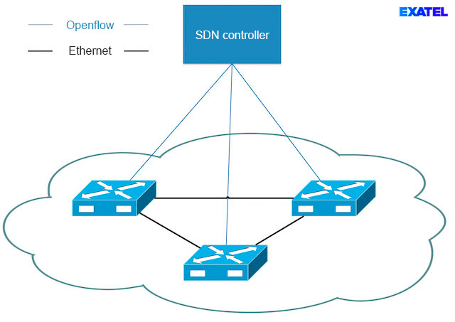
An OpenFlow agent is embedded within the devices, and initiates controller connections. SDN controller configuration must be introduced via an independent management channel. However, a single agent can maintain OpenFlow channels with multiple SDN controllers. Every channel is assigned one of 3 predicted roles: Slave, Master or Equal. Slave enables only reading available data. Master and Equal channels are authorized to read and modify flow rules and configure network mechanisms. Two configuration types are allowed – Master-Slave and Equal-Equal. Only one channel, and one SDN controller in consequence, can be assigned the Master role in the case of the first one. At the same time, all other channels must be assigned the Slave role. In the second case, all channels must be assigned the Equal role. TLS (Transport Layer Security) standard is used in order to protect OpenFlow channels.
OpenFlow protocol capabilities
The OpenFlow protocol enables:
- installation/deletion/modification of OF rules,
- installation/deletion/modification of OF groups,
- downloading statistics regarding OF rules, OF tables and OF ports,
- configuration of the meter mechanism implementing the network traffic flow policing function,
- downloading basic information of the OpenFlow switch.
The OpenFlow protocol operating model coincides with the SDN network reference model presented in the previous chapter, and the OpenFlow protocol itself implements the SDN controller – network resources interface, since it enables logical central control over OF switches.
OpenFlow switch control principles
An OpenFlow switch is controlled through installing OF rules in the format shown in Figure 4. A rule consists of a traffic flow definition (Match Fields), which determines the criteria to be satisfied by a frame, in order to be assigned to a given rule. The traffic flow definition is a list of structure-related entries {field/metadate name, mask, value}. Examples of such entries are:
- {IP_DST, 255.255.255.0, 45.3.233.0},
- {MAC_DST, FF:FF:FF:00:00:00, A2:A3:A4:00:00:00},
- {TCP_SRC, 0xCC00, 0}.
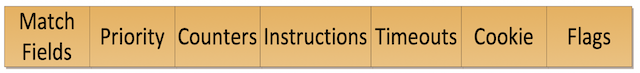
Figure 4 – OpenFlow Rule
A priority defines rule assignment sequence, should a given frame match the multiple rule definition.
Counters store information on the number of bytes, data frames and rule lifetime.
Instructions control the traffic by directing to successive datapath structure elements (the term datapath will be discussed in the following chapter) and executing actions that modify packet headers. Table 1 lists the instructions with descriptions, in the order of their execution when processing the OpenFlow rule.
Timeout fields contain counters defining when a rule is to be deleted. A rule can be removed after a certain inactivity period and after a specified time since installation. It can also be installed permanently.
The cookie field value acts as a rule identifier that can be used during modification, deletion or downloading rule statistics.
Flags determine how the rules are managed.
| Instruction name | Parameters | Description |
| WRITE METADATA |
Metadata value, mask |
Sets unmasked bits of metadata associated with processed frame. Metadata can be used in traffic flow definition field in successive OF tables. |
| METER | Meter ID | Forwards the frame onto the Meter policing mechanism. Frames not rejected by the meter are subject to the execution of subsequent instructions from the processed OF rule. |
| APPLY ACTIONS | Action list | Successively executes actions in the action list constituting an instruction parameter. Action list can contain repetition of the same action (e.g., multiple adding of the MLPS header and setting the MPLS label value). |
| CLEAR_ACTIONS | – | Removes all entries of the action set associated with a given frame. |
| WRITE ACTIONS | Action set | Adds actions from the set given as an argument to an action set associated with the given frame. |
| GOTO TABLE | OF table number | Redirects the frame for further processing within an indicated OF table. |
Proactive and reactive control
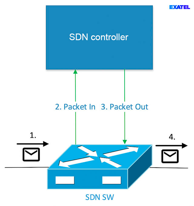
The OpenFlow protocol enables two control methods – proactive and reactive. Proactive control involves installing OpenFlow rule instructions prior to receiving matching data frames. Packets not matching any of the installed flow rules are rejected. Such an approach is applied in IP networks. Routing protocols acting as IP router control layers based on exchanged route information determine an RIB (Routing Information Base) table, which contains a list of available subnetworks and assigned metrics and output ports. Next, the RIB is mapped onto an FIB (Forwarding Information Base) packet switch table, which contains the best routes to each subnetwork. Received IP packets are then forwarded as per the FIB, and the ones not matching any of the available entries are rejected. Reactive control involves determining an output interface for a packet upon its reception. Reactive control in OpenFlow is executed through the use of packetIn and pakcetOut messages and installing an OpenFlow rule sending the packets that do not match any of the other installed rules to the SDN controller. Figure 5 shows the exchange of messages accompanying packet handling in the case of reactive control. When an OpenFlow switch receives a packet not matching any of the installed SDN controller rules, a packetIn message is sent, which contains the entire Ethernet frame or its part, and an identifier of the buffer where the entire frame is sent. After making a decision on the further fate of the frame, the controller sends a packetOut message to the switch, which contains the received frame or buffer identifier, and, optionally, installs an OpenFlow rule for successive packets of the same network traffic flow. An example of reactive control in traditional networks is the Ad-hoc On-demand Distance Vector (AODV) protocol used in wireless ad-hoc networks. The OpenFlow protocol enables combining both control methods, through the implementation of some functionalities in a proactive manner and some in a reactive manner.
OpenFlow is a binary protocol that positively translates to the rate of message processing by the CPU. An important feature of OpenFlow is its expandability enabling. This is described in the next article on our blog.
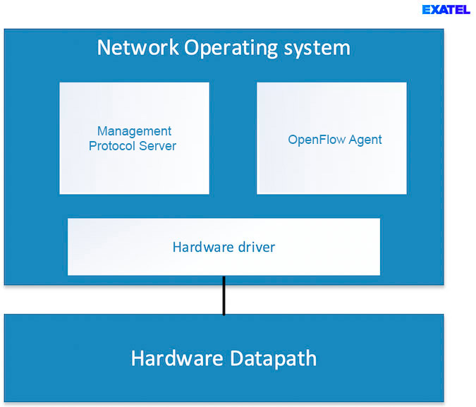
OpenFlow Switch
The OpenFlow Switch consists of the OpenFlow protocol agent, Datapath and a management protocol server. The high-level structure of the hardware switch is presented in Figure 6. This agent is responsible for handling OpenFlow channels and controlling the datapath as per the requirements of the SDN controller. The agent is a daemon running on the OF switch operating system – NOS (Network Operating System). The datapath is a set of components responsible for processing and forwarding packets. It consists of OF rule tables, OF group tables, QoS mechanisms and ports. Its execution can be based on hardware, in the case of physical switches or software, in the case of virtual switches (e.g., Open vSwitch). In the case of hardware-based switches, a device controller is an essential component for integrating the operating system with hardware components executing the datapath. The OF standard does not impose the application of a management protocol, however it is usually necessary since OpenFlow enables managing only a part of switch resources. The management protocol can be freely chosen by the device manufacturer.
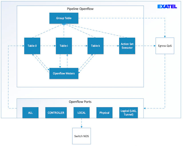
OpenFlow switch datapath is visualized in Figure 7. Dashed lines show the most important possible packet transitions between traffic processing components. A packet is directed from the port to table 0. Next, together with the matching OF rule, it is forwarded to another OF rule table or a group table. The packet may pass any number of tables, but only in the direction of increasing table indices, i.e., it is allowed to move from table 0 to 12, but not from 12 to 3. In particular, the packet may be processed only in one OF rule table. It can, however, be redirected from each OpenFlow table onto the meter policing mechanism. Packets rejected by the policer are subject to successive instructions saved in the OpenFlow rule. 3 types of metadata are forwarded together with the packet:
- input port number,
- 64b of OpenFlow metadata to be utilized by the user,
- set of actions executed at the end of packet processing pipeline.
Matching in OpenFlow
The input port number and OF metadata can be used to match a packet to an appropriate OF rule (matching). OF metadata can be changes in the course of processing in an OF table using an appropriate instruction, which enables carrying additional information between tables. An action set can be supplemented in the course of passing through each table. This can be achieved with the WRITE_ACTIONS instruction. An action set can contain one action of a given type each, and subsequent additions of the same action result in it being overwritten, i.e., if table 0 has an action, which sets the MPLS header label field to 100, and then the same action setting the field to 200 is added in Table 10, the ultimate value will be set to 200. Furthermore, it is possible to immediately execute an action when processing in an OF rule table through the APPLY_ACTIONS instruction. The packet can be redirected to a group table both from the OF rule table, as well as based on actions saved in the action set. OpenFlow groups and their utilization will be discussed in one of successive articles. A block of output QoS mechanisms is also an optional block within a packet path. The enqueue action is used to redirect the packet to a QoS queue.
Pipeline in OpenFlow
Two OpenFlow switches are distinguished – OpenFlow-only and OpenFlow-hybrid. They differ in terms of the presence of a traditional packet processing pipeline, which is available only in hybrid switches. The packet processing pipeline is a path composed of packet processing blocks, which the packet passes within a network device. In the case of an OpenFlow switch, a pipeline consists of a list of OpenFlow tables. Pipeline structure does not only depend on switch structure, but also on the installed flow rules, since OpenFlow rules contain information on transitions to successive OF tables. As a result, pipeline structure depends on the SDN app controlling the traffic in the network, as well as the type of packet and its source.
A traditional pipeline may implement, depending on the implementation, switch Ethernet or IP routing. A pipeline can be selected for a given packet in a hybrid switch through a classifier, and be redirected from an OpenFlow pipeline to a traditional pipeline using special logic output ports;
- NORMAL port redirecting to a traditional pipeline input or
- FLOOD port broadcasting the frame according to a traditional pipeline, e.g., only onto other ports of the same VLAN.
The greatest downside of the OpenFlow standard is the high number of optional mechanisms. In consequence, devices compliant with the specifications published by ONF are often not fully compatible with each other. A rough definition of a standard implies the need to thoroughly verify the device’s capabilities prior to using it in an OpenFlow network. However, this is natural since, just like in conventional networks, and in the case of SDN, a given device is dedicated to a specific network type (data centre, enterprise, ISP), and each network type has different requirements.
Summary
SDN network based on the OpenFlow protocol are a real alternative to traditional packet-based networks. Owing to protocol expandability with any headers, OpenFlow switch manufacturers have the option to design devices for any application. The protocol has all the pros and cons of central control, i.e., it enables better decision-making and simplification of network devices, but has a logically central failure point (SDN controller). It should be noted that an SDN controller is a logically centralized components that can consist of numerous system instances operating within a cluster.
[1] ,,Framework of software-defined networking”, ITU Y.3300, 2014